Heavy-Lift Medical Payload Quadcopter
End-to-end design and delivery of a custom heavy-lift drone in a two-person team: 15 lb of refrigerated payload, twenty minutes of flight, built for under $5,000 against a $14,000 commercial platform.
- Take-off
- Waypoint 01
- Waypoint 02
- Descend
- Release
- Return to home
- Land
A simulation of the planned delivery profile, not logged telemetry: the figures are computed from the mission plan, and the vertical scale is compressed so a 1.28 m aircraft stays visible over a 42 m cruise. Drag to orbit.
- Heavy-lift quadcopter — key dimensions
- 15 lb — Insulated payload, isolated mount
- Ø34 in — Two-blade, washout to the tip
- Ø40 CF — Roll-wrapped, folding joint
- Swappable — Outside the enclosure by design
Evidence
- 18.5 kgAll-up massdesign band 18.25–18.75
- 1.7–1.8Thrust : weight
- 15 lbPayloadrefrigerated
- 20 minEndurance
- Ø40 mmArm tube3K roll-wrapped CF
- 34 inRotortwo-blade
- 1,280 mmMotor-to-motor
- <$5,000Bill of materialsexcludes labour
Case study
The problem
- A client needed 15 lb of temperature-controlled medical payload moved by air, and the off-the-shelf platform that could do it cost $14,000.
- Two of us, one summer, and a budget that ruled out buying the answer.
- The payload is the awkward part: a vacuum-insulated box is heavy, rigid and has to stay clipped on through a hard landing.
The design
- Quad-X on Ø40 mm roll-wrapped carbon arms with aluminium folding joints at the roots — the aircraft has to fit in a vehicle.
- 34-inch two-blade rotors sized for a thrust-to-weight of 1.7–1.8 at an 18.25–18.75 kg all-up design band.
- Payload slung under the belly on isolators, with a second isolated mount under the flight controller, deliberately tuned apart.
- Battery outside the enclosure, so it swaps between sorties without opening anything.
What I did
- Ran the propulsion trade study — motor, prop and cell-count combinations against thrust margin, endurance and cost.
- Designed the payload bracket, the isolator layout and the field quick-release.
- Full electrical integration: flight controller wiring, ESC configuration, power distribution and the current-sensing path.
- Sourced across India and China and held the bill of materials under $5,000.
How it was tested
- Thrust per motor measured on a bench against the sizing model — the payload and endurance figures are that model, validated at the motor.
- Isolator tuning checked against controller vibration logs, box loaded and empty. That is how the two mounts ended up separated by frequency.
- Failure modes exercised on the ground: link loss, GPS loss and low battery all trigger return-to-home above obstacle height.
- No flight-test log is published here, because the programme described is a bench and ground programme.
Result
- The payload and endurance specification of a $14,000 commercial platform, on a bill of materials under $5,000 — excluding our own time.
- 15 lb refrigerated payload, 20 minutes of flight, delivered end to end by two people.
The hardware
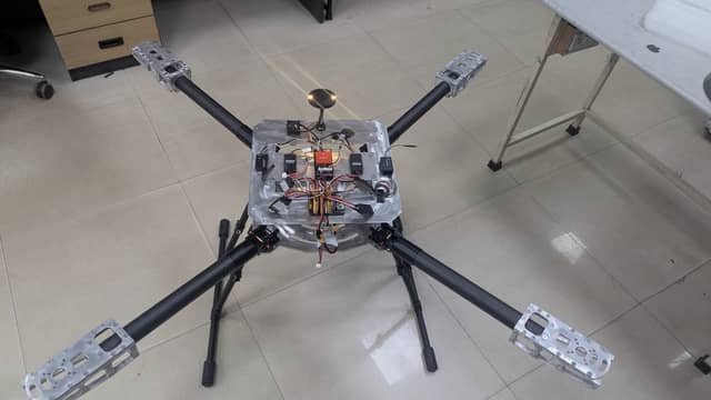
The aircraft on its legs. Ø40 carbon arms into machined mounts, avionics on the upper deck, the payload hardpoint underneath. The design is published; the bill of materials is not. - Workshop
Assembled, on the bench. For scale: that is a 1,280 mm motor-to-motor diagonal. A short clip panning around the finished heavy-lift quadcopter standing on a workbench in a workshop.

Most of the difficulty sat in the mount rather than in the box. Hanging 6.8 kg off a flexing carbon deck without feeding vibration into the flight controller — and doing it so a technician can unclip it in a field — took longer than anything else on the aircraft. The payload bracket sits on isolators, the controller sits on a second set, and the two are tuned apart.
Almost everything downstream of that was a cost decision. We paid on the structure, the propulsion and anything in the power path, and saved everywhere else.
Decisions
- 01
Why fold the arms?
A 34-inch rotor sets a 1.3 m diagonal, and a rigid airframe that size does not fit in a vehicle. Tube joints at the roots close it down to something two people can carry, and put the joint at the one place on the arm where the bending moment is reacted by the frame rather than by the tube.
- 02
Why is the safety switch only on motor power?
Cutting the whole system at the switch reboots the flight controller, and the GPS re-acquires and the compass re-initialises every time somebody arms on the pad. Motor power goes through the switch; the avionics stay live off the distribution board.
- 03
What happens when the link drops?
Return-to-home climbs above the tallest obstacle on the route, tracks back and lands — same routine for comms loss, GPS loss and battery. The battery case triggers at 50 % remaining, which is not a reserve being thrown away: the mission is out-and-back on a three-minute outbound leg, so 50 % is what guarantees the return is flown on charge the aircraft has already proved it has. The 20 minutes is total endurance, not the half you are allowed to spend going out.
⚠ Client work, under confidentiality. The design is published; the bill of materials is not — no part numbers, suppliers, prices or manufacturers appear anywhere on this site.