Vision End Effector & Robot Tending Cell
A camera-equipped modular tool mount on a quick-change interface — one flange carrying a gripper, a MIG torch, a spot welding gun or a rotary atomiser — and the tending cell that put it to work.
Drag the green target and the arm solves for it — cyclic coordinate descent into a 125 Hz servo under real velocity, acceleration and jerk limits, so it falls behind on a fast drag and catches up when you stop. It will not drive through the bench. Drag anywhere else to orbit.
- Vision end effector — key dimensions
- Ø50 · 4 × M6 — ISO 9409-1-50-4-M6 flange
- ±2 % FS — In-line torque sensing
- Ø26–38 mm — One tooling set · 40 % of commercial caps
- Vision — Coaxial ring light on the tool
Evidence
- ±0.1 mmTCP residualfour-approach check
- Ø50FlangeISO 9409-1-50-4-M6
- 4 × M6Bolt circleØ31.5 PCD
- Ø6 H7Dowelangular datum
- Ø26–38Jaw range, mm40 % of commercial caps
- −5 %Manufacturing costper assembly, vs manual
- 4Tools, one mount
Case study
The problem
- Bottle caps arrive in a range of diameters and each one needs a threaded fastener applied to a controlled torque.
- A fixed socket handles one cap size. Change the product and you change the tooling, which is the cost nobody budgets for.
- A cell that only taps is a cell that needs a second station to inspect what it just did.
The design
- One tool mount to ISO 9409-1-50-4-M6 — Ø50 face, Ø31.5 bolt circle of four M6, Ø6 H7 dowel setting the angular datum.
- Three jaws on a scroll ring, Ø26–38 mm — 40 % of the commercial cap range — with no tooling change.
- In-line torque sensing between flange and head, so every fastener is measured rather than assumed.
- Camera and coaxial ring light on the tool. Robot tending cell around it: one arm, two stations, inside a fenced enclosure.
What I did
- Designed the adjustable mounting system and the tapping head around the cap-diameter range.
- Designed the camera-equipped end effector on the quick-change interface — applicable across arc welding, spot welding, painting and pick-and-place.
- Calibrated six-axis robots: TCP residual within ±0.1 mm over four approach directions.
- Field analysis at the Honda plant in Tapukara, Rajasthan — how automation gets deployed, rather than how it is specified.
How it was tested
- TCP checked from four approach directions onto a reference point. It is a calibration residual, not an absolute positional accuracy figure, and is labelled that way throughout.
- Cap-size coverage measured against the client’s commercial range — Ø26–38 mm out of it, which is where the 40 % comes from.
- Cycle costed against the manual process it replaced.
Result
- TCP calibration residual within ±0.1 mm over four approach directions.
- One set of tooling spans Ø26–38 mm — 40 % of the commercial cap range — with no changeover.
- Per-assembly manufacturing cost down 5 % against the manual process.
On the floor
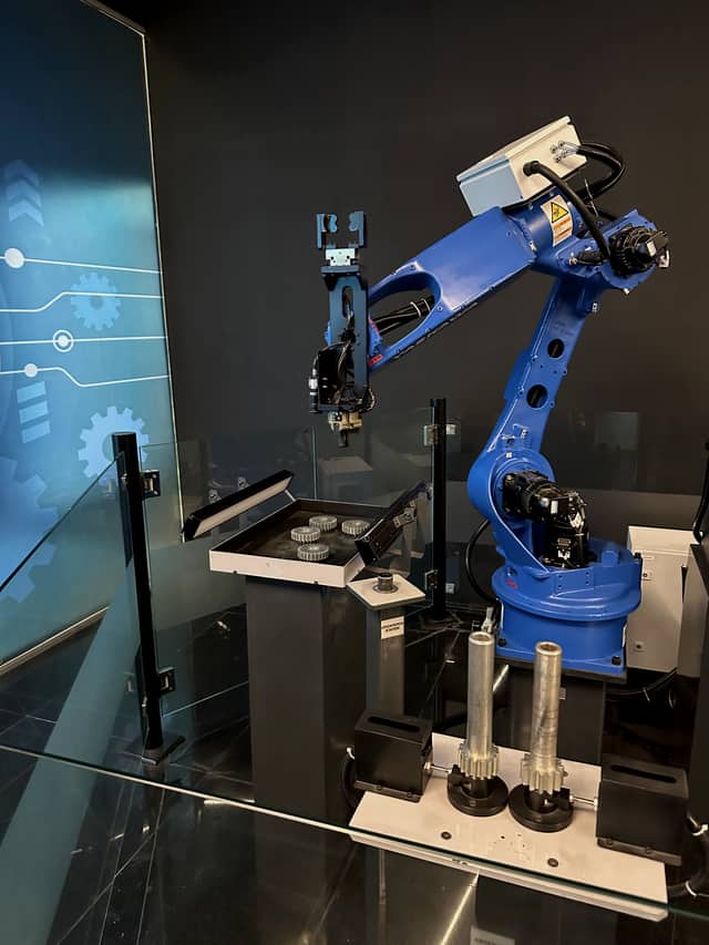
The job itself: caps on a tray, bottles staged below. Cap diameter is the variable everything else has to accommodate, which is why the head ended up with an adjustable jaw ring rather than a fixed socket. 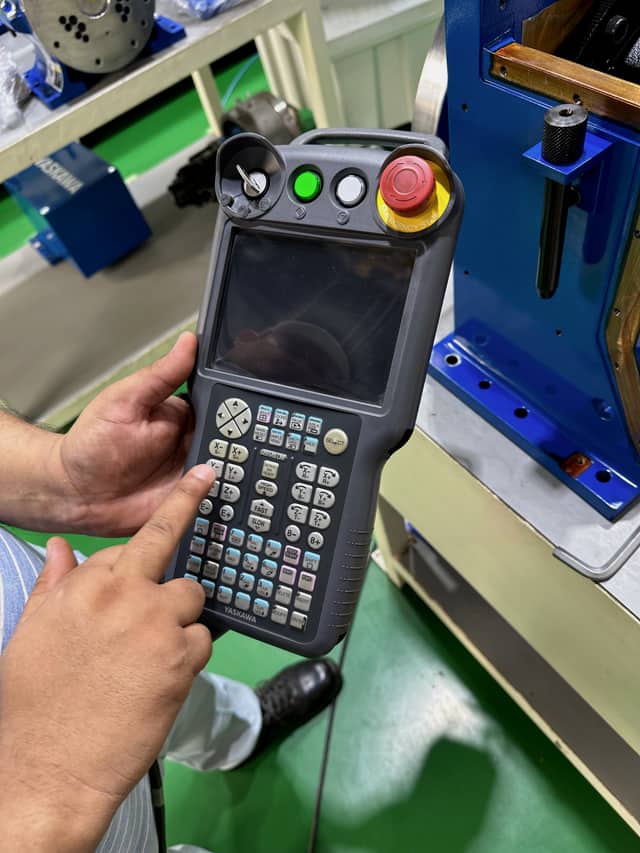
Jogging the robot on the pendant. Tool centre point calibration is done exactly like this: drive the tool onto a reference point from four approach directions and let the controller solve for the offset. 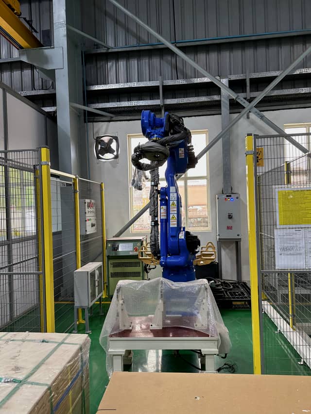
Inside the guarding. The tending cell I designed puts one arm between two stations inside an enclosure like this one, which is what makes the reach envelope a hard constraint rather than a preference. 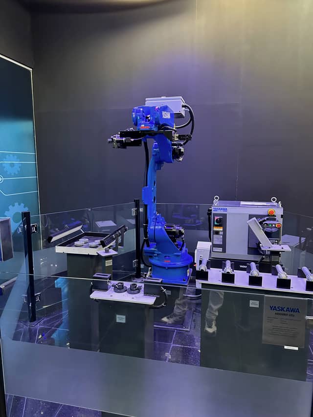
An assembly cell running a tool-carrying head over a tray of parts. One mount, several jobs — the arrangement the quick-change interface exists to serve. 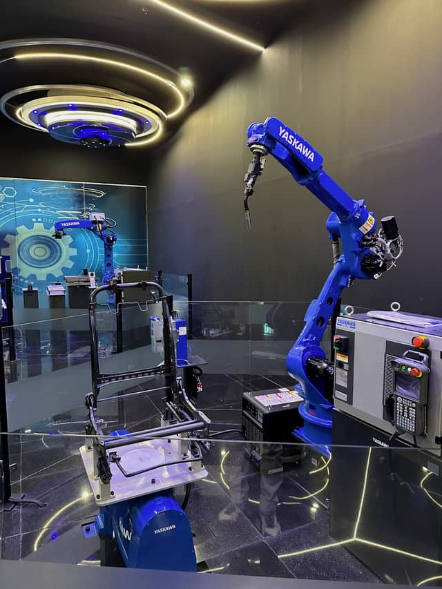
A tubular frame in its fixture. Every one of these needs the tool to arrive at the same point every cycle — which is the whole argument for the dowel in the flange. 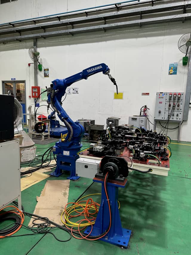
A torch-equipped arm over a multi-station welding fixture. This is the environment the cell had to survive — not a lab.


The interface is the credential. ISO 9409-1-50-4-M6 — Ø50 face, Ø31.5 bolt circle of four M6, Ø6 H7 dowel on the angular datum — means a tool built to it mounts on any arm from any manufacturer. That is the difference between a product and a one-off fixture.
The camera is what changes the job. A fixed camera sees one view; on the tool it sees wherever the arm can reach, so the same hardware inspects the part before the jaws close and again after the torch has been over it.
The number from the other half of the placement is a Tool Centre Point calibration residual: ±0.1 mm, taken by driving the tool onto a reference point from four approach directions. TCP residual, absolute positional accuracy and repeatability are three different quantities and only the first was measured — which is the one that matters here, because a changer that does not return to the same point has to be re-taught on every swap.
Decisions
- 01
Why a quick-change interface at all?
A cell that welds and then inspects and then picks is three cells unless the arm can change what it is holding. The changer is what collapses three fixtures into one.
- 02
Why the dowel?
Four bolts on a circle locate the tool concentrically but do nothing about rotation — you can bolt it on four ways. The Ø6 H7 pin makes only one of them possible, which is the difference between a repeatable TCP and a re-teach.
- 03
Why put the camera on the tool?
A fixed camera sees one pose. A tool-mounted camera sees every pose the arm can reach, which means pre-pick inspection and post-weld inspection run on the same hardware with no second station.
⚠ The arm rendered here is generic: correct six-axis kinematics, no manufacturer’s proportions, branding or trade dress. Field analysis was carried out at the Honda plant in Tapukara, Rajasthan.